CPI100UC (Nimrod, ICP) Countertop Water Filter Installation and Conditioning Instructions
Manufactured by: Fairey Industrial Ceramics Limited, England
Parts Availability
Important - Always use genuine replacement elements and components to guarantee the manufacturer's performance claims. Spare Imperial Ultracarb cartridge part #W9123085.
Operating Parameters
- Maximum Working Pressure*: 690 Kpa (100psig)
- Maximum Working Temperature: 38°C (100°F)
- Minimum Operating Pressure: 69 Kpa (10psig)
- Minimum Operating Temperature: 5°C (41°F)
Carton Contents:
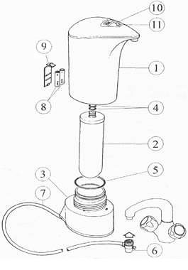
The Doulton CPI100UC (Nimrod, ICP) Countertop Water Filter carton contains the following for assembly:
- Countertop main body
- Doulton 212 mm Candle (with 2 fitted 'O' ring seals)
- Lower bowl (with 'O' ring seal and fitted flexible tube assembly)
- Size AAA 1.5 volt batteries x 2
- Battery cover
- Set of 2 faucet spout adapters
1.0 Installation:
1.1 Selecting a position for the filter
The filter is designed to be free standing on a sink unit or adjacent work top. WARNING: For cold water only
1.2 Fitting the Ceramic Element
Wash and dry your hands thoroughly, ensuring that any open cuts are covered, to prevent contamination of the filter cartridge and housing. Separate the main body (1) from the lower bowl (3) Remove the ceramic cartridge (2) from it's protective sleeve and check that the 2 cartridge sealing 'O' rings (4) are securely in place in the grooves on the ceramic cartridge mount. Moisten the 0' rings (4) with a little boiled and cooled water. Push the cartridge (2) firmly into position in the internal boss of the main body (1). Check that the '0' ring (5) is correctly in place in the groove of the lower bowl (3) and place the thread of the main body (1) over the thread of the lower bowl (3). Using the specially designed recessed hand grip, located underneath the lower bowl, turn in a clockwise direction until the two parts are firmly fitted together and cannot be tightened further without excessive force. The spout and the inlet tube should be pointing in opposite directions and there should be no obvious gap between the main body and the lower bowl.
1.3 Fitting the Flowmeter Batteries
Remove the batteries (8) from the plastic bag. Open the battery cover (9) and push the batteries into position carefully observing the + and - directions indicated in the battery recess. Once the batteries are correctly in place, replace the cover. See section 3.0 for use of the flow indicator.
N.B. There may be occasions where the batteries require replacing before the flowmeter indicates that the filter cartridge is exhausted, this is indicated by a loss of display. In these circumstances the batteries require replacing immediately. On fitting new batteries if the reset button is NOT pressed the memory retains the capacity status and the capacity countdown will continue. If the reset button is pressed, the memory will be lost and the capacity will revert to 100%. If this happens, it is important to replace the ceramic cartridge, to ensure that the existing cartridge is not accidentally over used.
1.4 Connecting the Pipework
Take the diverter (6) and pipework (7), if an appropriately sized male thread is visible, screw the collar of the diverter valve (6) anti-clockwise, as viewed from above, onto the cold or mixer tap. Hand tighten only. If the thread on the diverter (6), does not match that of the tap, it may be necessary to use an appropriately sized adapter, to convert the faucet to the same thread as the diverter valve.
2.0 Conditioning the Filter
The filter should now be ready for filling with water. To avoid any problems caused by airlocks in the filter housing, the unit should be held upside down over the kitchen sink. Partially turn on the cold tap, then turn the lever on the diverter valve (6) to allow the water to gently fill the unit for the first time. Check that there are no leaks from the join between the main body (1) and the lower bowl (3) or from the diverter valve, which could be caused by the threads not being correctly engaged. During the first fill, it may take some time for water to appear through the outlet spout. Once the unit is full, it can be placed upright on the worktop. Allow the water to run to waste for a minimum of 10 minutes and then stand the filter unused for 24 hours to condition it to the source water. After the 24 hour stand, flush the filter with a further 3 litres (approx. 1 US Gallons) of water to waste, after which the filter is ready for use. If the filter is fitted with a cartridge containing carbon or other water treatment media, for optimum performance, run the filter at or below the recommended service flow to the capacity stated - see the table on the accompanying box.
3.0 Electronic Flowmeter and Indicator General Features
3.1 Use of the Display Button (11)
3.11 In 'flow' mode the flow rate in US Gallons per minute or litres per minute is automatically displayed.
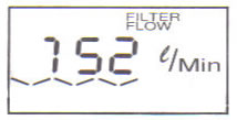
If the Display Button is held down for more than 4 seconds, then the units of flow measurement will change from litres to US gallons and vice versa.
3.12 In the 'filter life' mode the flow indicator will count down from 100 and the lifetime remaining on the filter cartridge is displayed. To switch between the flow or filter life mode simply press the Display Button.
3.13 On reaching zero life, the words: 'CHANGE FILTER' will automatically illuminate and flash at 1 second intervals in either display mode indicating when to replace the filter cartridge.
3.2 Use of the Reset Button (10)
Important: Please read this instruction fully before using the Reset Button.
The Reset Button is only to be used to reset the flowmeter memory to full capacity when the ceramic element is replaced. Using a pointed object e.g. the sharp end of a pencil, press the Reset Button (10) ONCE. Do not hold the button down, as this will corrupt the memory of the Flow Indicator.
IMPORTANT: The capacity recalled by the Reset Button is only valid for the type of cartridge supplied with the filter unit. Therefore the replacement element fitted, must be the same model of cartridge as was originally supplied with the unit.
4.0 Use of the Diverter Valve
The diverter valve allows filtered water to be drawn off from the outlet spout of the filter unit, by turning the diverter valve lever.
To draw off unfiltered water from the kitchen faucet, turn the diverter valve lever and turn on the water supply at the faucet to allow the water to be directed to the kitchen faucet.
To switch back to filtered water simply turn the diverter lever back to allow water to flow from the filter unit.
5.0 Servicing the Filter - Changing or Cleaning the Filter Cartridge
During use, in certain water conditions, the flow rate may deteriorate and the ceramic cartridge will require cleaning to restore the flow rate, which should be carried out as follows:
IMPORTANT: Ensure that any open cuts are covered when handling the used filter cartridge and always wash your hands thoroughly after servicing the filter.
With the cold tap turned off, hold the filter unit over the sink. Unscrew the main body (1) from the lower bowl (3) - care must be taken as the housing will be full of water and there will be a minor leakage. The cartridge (2) can be gently pulled from the upper body and cleaned in accordance with the operating and exchange instructions, or replaced as described in section 1.2.
If a new cartridge has been installed, recondition the filter as described in section 2.0, always remember to reset the flowmeter memory by a single press of the Reset Button. It is advisable to replace with new batteries on fitting a new cartridge.
6.0 Cleaning the Filter Housing
IMPORTANT: Do not allow water to penetrate the control buttons, the battery cover or the flow indicator display lens.
Wipe the filter housing clean using a soft cloth, dampened with hand warm water. Avoid using bleach or strong detergents and abrasive pads as these may damage the surface of your housing.
*Pressure information
The filter housing has been tested for structural integrity and is rated for use as directed at pressures up to 100psig. If there is any chance that the filter will be exposed to pressures above 100psig then an approved pressure reducing valve set at 100psig should be installed upstream of the tap to eliminate any extreme variations in pressure.
Doulton, making the world's water safe to drink since 1827. The early innovation associated
with the Doulton name has continued well into the twenty first
century with an increasingly sophisticated range of water
filtration products being developed to meet the needs of modern
water purification systems. Today, Doulton is acknowledged
world leader in water purification, with over a million systems
sold each year in over 150 countries.
Home Water Filters
Commercial Kitchens Equipment
Industrial Water Purification Systems
Portable Gravity Units
Boats/RV Fresh Water Systems
Other Doulton Ceramic Filter Applications
Water Filter Replacement Ceramic Cartridges/Candles
ALL PRODUCTS LIST
| 